NR↗Nicholas
Rochwerger
Portrait of Nicholas Rochwerger

McGill University
B.Eng. Mechanical Engineering · 2026

A little about me

Start with the function.
Build upward.

I break a complex problem into the things the system actually needs to do, then find a direct mechanical way to achieve each one.

My work combines standard hardware where precise mechanical behavior matters with custom geometry where the assembly needs a shape no catalog part provides. I’m interested in mechanical design and medical device opportunities where that thinking can become useful physical products.

Design & making

Mechanism design · SolidWorks · AutoCAD · Revit · FEA · FDM/SLA printing · Rapid prototyping · CNC machining

Software & hardware

Python · MATLAB · Java · Arduino

Mechanical engineer · McGill ’26

From complex
problems to
working hardware.

I’m Nicholas Rochwerger. I design mechanisms, build prototypes, and turn ideas into assemblies you can put your hands on.

Mechanical design / Medical devices / Robotics

Explore my work
01 — Featured prototypeMcGill SuPER Lab
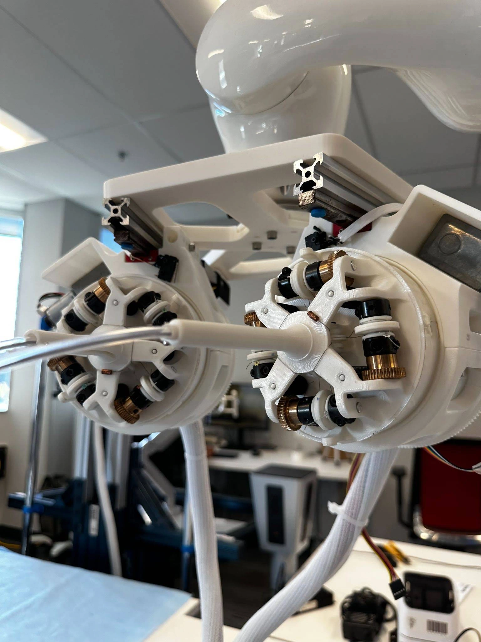
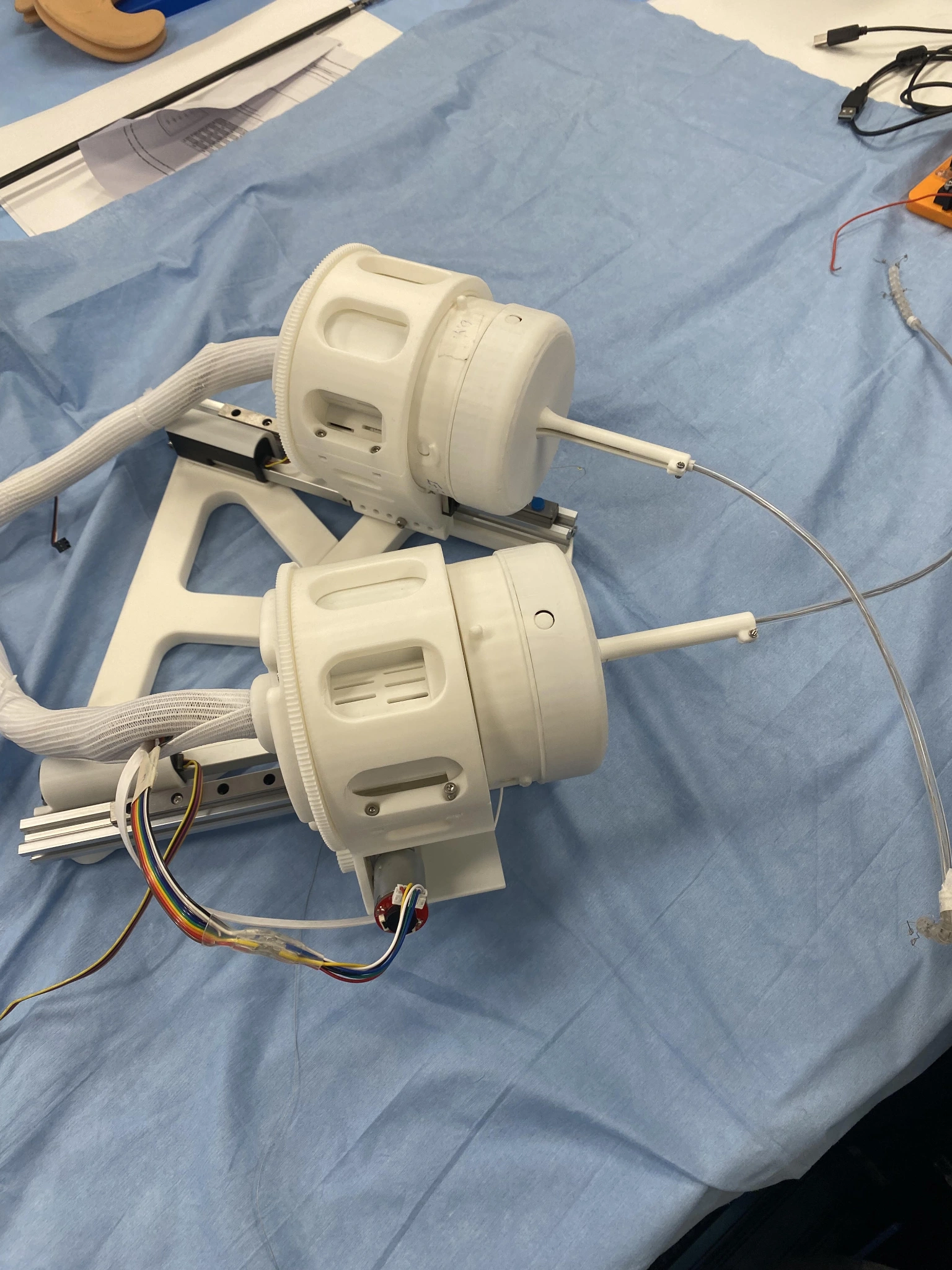
White 3D-printed tendon-drive cassettes, capstans and mechanical frame of the ENT robot prototype
PORTABLE ENT ROBOTDesign → CAD → Prototype
Mechanism designCAD & fabricationDesign for assemblyPhysical prototyping

01 / McGill SuPER Lab

Medical robotics · Capstone

A compact platform.
A more flexible approach.

A portable, tendon-actuated continuum robot for the tight, curved anatomy of ear, nose and throat procedures.

Our multidisciplinary team developed and assembled a physical prototype, then demonstrated it on a medical mannequin. The project received the McGill Engine Capstone Design Prize.

My contribution

Led physical product development: mechanical hardware design, CAD, custom 3D-printed components and assembly of the complete mechanical system.

Team achievement

Integrated a tendon-actuated platform and demonstrated the assembled prototype on a mannequin.

Prototype evidence: mannequin demonstration. Clinical safety, sterilization and performance validation are not established by this work.

Prototype / Motion demonstration

See the flexible
tool change shape.

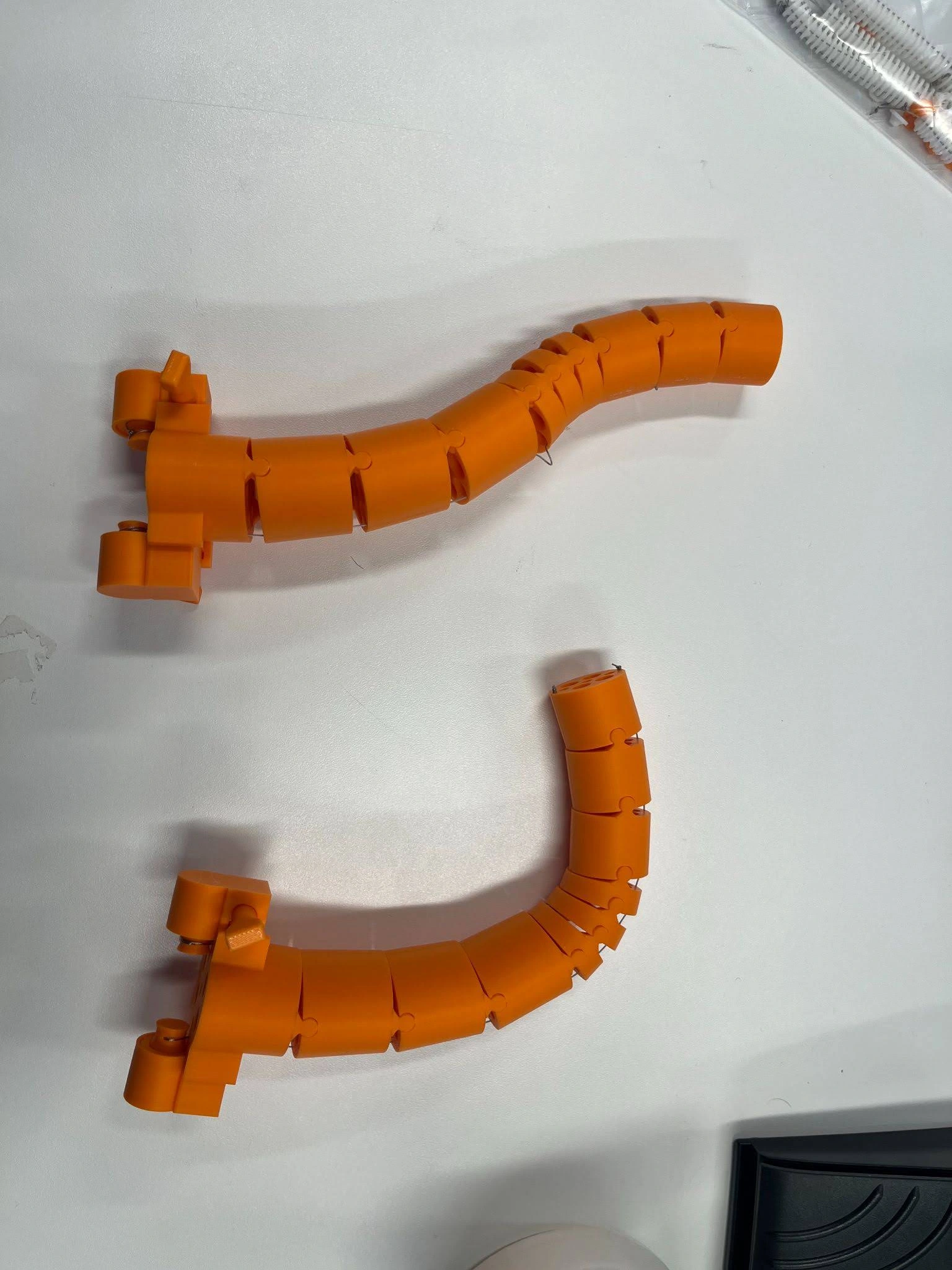
The segmented distal tool bends left, followed by a closer view of its changing shape during the mannequin setup demonstration.

Continuous footage at original speed.

Flexible-tool motion · Open video ↗

01.1 / Cassette configuration

Route the tendons.
Keep the freedom.

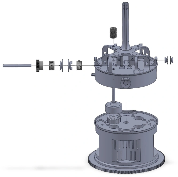
A two-segment, S-curving tool needed compact tendon routing, with rotation and horizontal translation of the complete system.

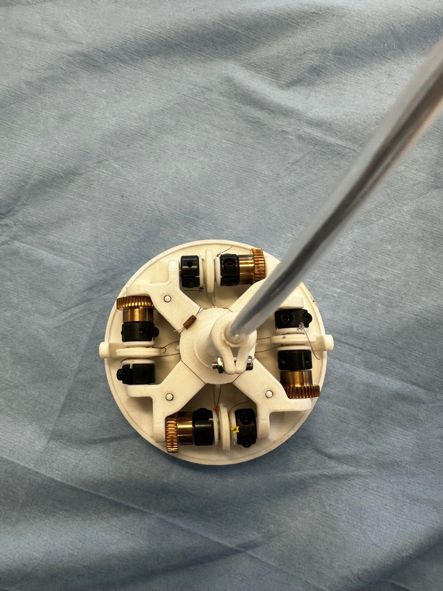
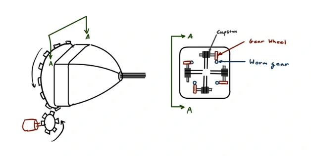
I established a four-way radial layout: four drive units, each with counter-oriented capstans on a single shaft, actuate eight tendons. An external gear interface rotates the body; a linear rail translates the assembly.

The architecture combines S-curve actuation with global reorientation, and is mirrored for a second tool.

4 drive units8 tendons per cassette
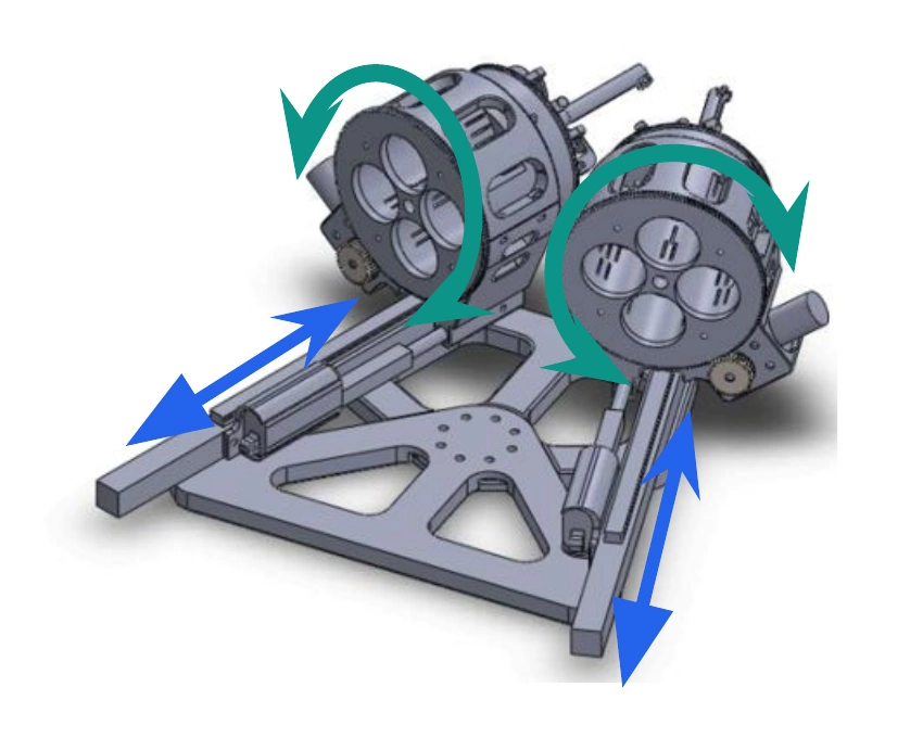
CAD of two cassettes on linear rails, with original teal rotation arrows and blue translation arrows
Rotation + translation, shown with the original annotations.
Inspect the cassette assembly
Exploded cassette CAD showing its radial drive layout and motor housing
Exploded assembly
Top view of four worm-gear drive units surrounding the tool shaft
Physical four-way layout

01.2 / Capstan torque transfer

Let steel grip.
Let the print shape.

The capstans needed to be removable and adjustable, while transferring worm-gear torque without relying on a complex machined part.

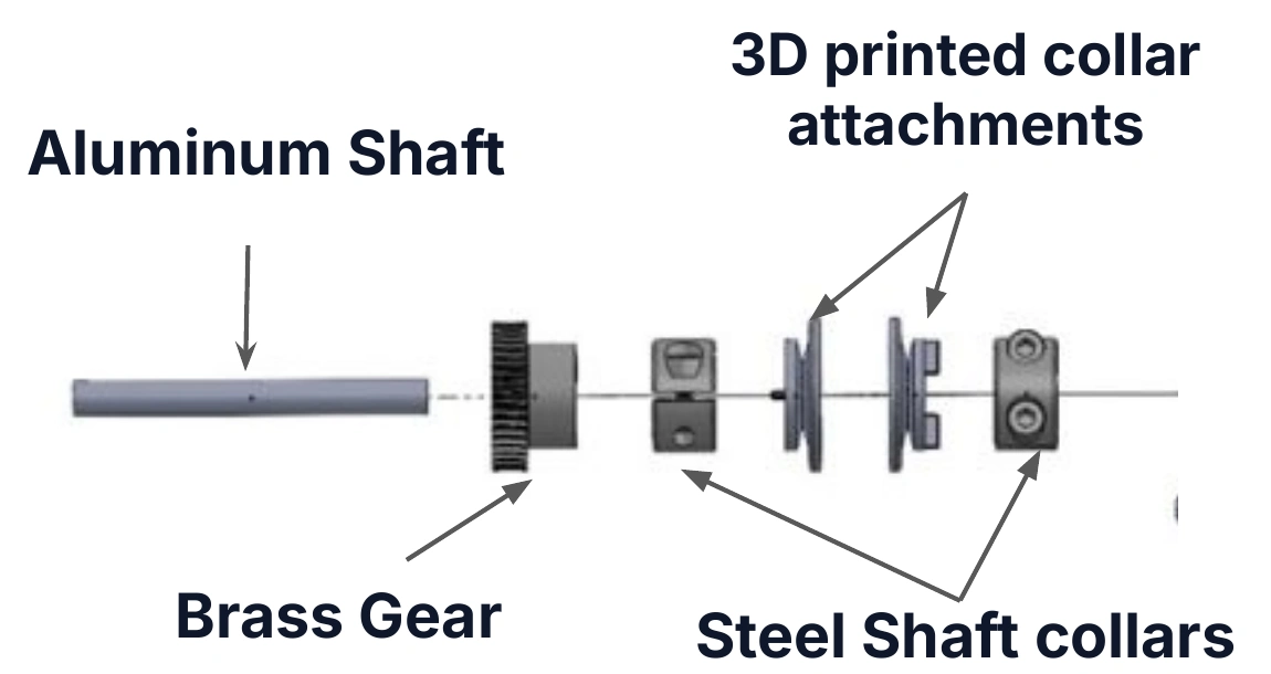
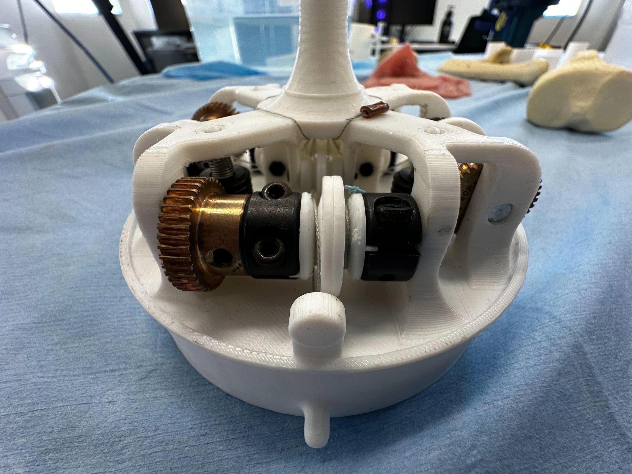
I separated shaft grip from tendon geometry. A catalog two-piece steel shaft collar clamps the aluminum shaft. A custom printed attachment holds the tendon; its flange engages the collar’s internal grooves.

One standard collar and one custom print create the torque path and tendon tie-off, with the functions handled by the parts best suited to them.

Annotated exploded torque-transfer shaft: aluminum shaft, brass gear, 3D-printed collar attachments and steel shaft collars
Separate the functions. Make the torque path visible.
Close-up of brass worm gear, black steel shaft collars and white printed capstan attachments
The same assembly, built.

01.3 / Motor–cassette interface

Design the connection
around the handoff.

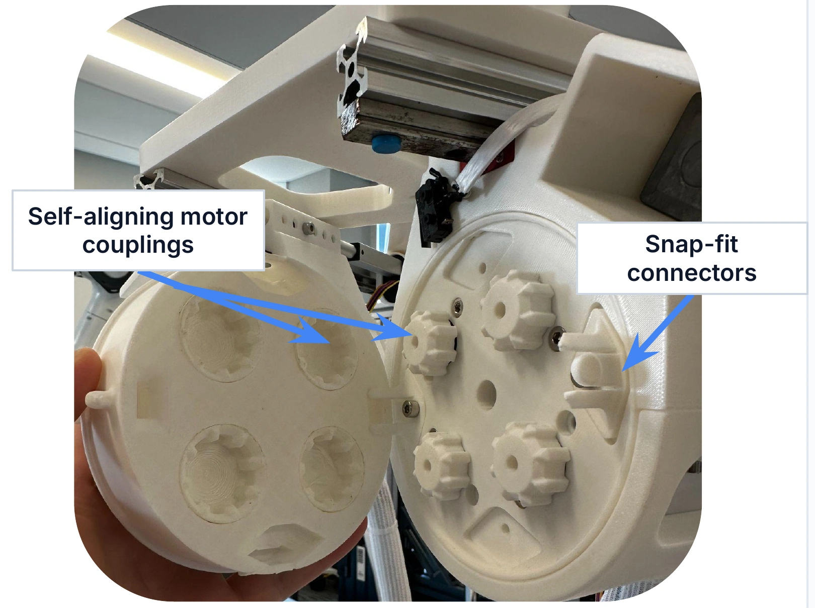
The design brief called for a disposable, sterilizable cassette and reusable drive motors. That separation needed a quick-release mechanical connection.

I designed couplings with angled guide grooves to bring the mating components into rotational alignment as they are pushed together, alongside snap-fit connectors for attachment.

The prototype integrates alignment into the connection itself, reducing the need for a separate manual alignment step.

Disposability and sterilizability were design requirements; this prototype does not demonstrate validated reprocessing or clinical use.

Separated motor housing and cassette, with original blue arrows labeling self-aligning motor couplings and snap-fit connectors
A reusable drive. A removable cassette. An interface that guides alignment.

01.4 / Surgical insertion sheath

Give a flexible tool
a structured path.

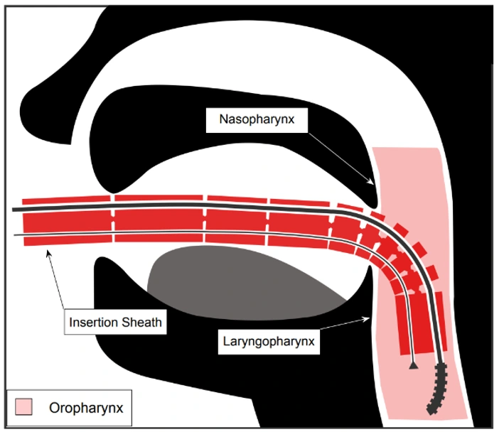
Flexible catheters need structural guidance. I designed an all-plastic, anatomically contoured sheath with snap-fit segments and internal channels for the catheter and borescopes.

The segments assemble by hand without secondary fasteners. The channels route the tools and optics together, supporting the flexible instruments through the curved corridor.

02 / Stereoscopic borescope holder

Mechanical design · Medical robotics prototype

Two parallel views.
One controlled adjustment.

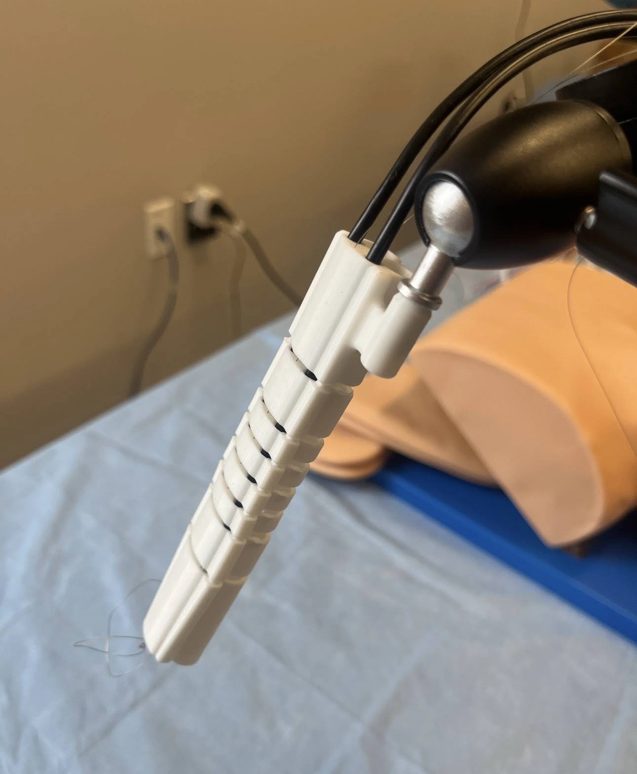
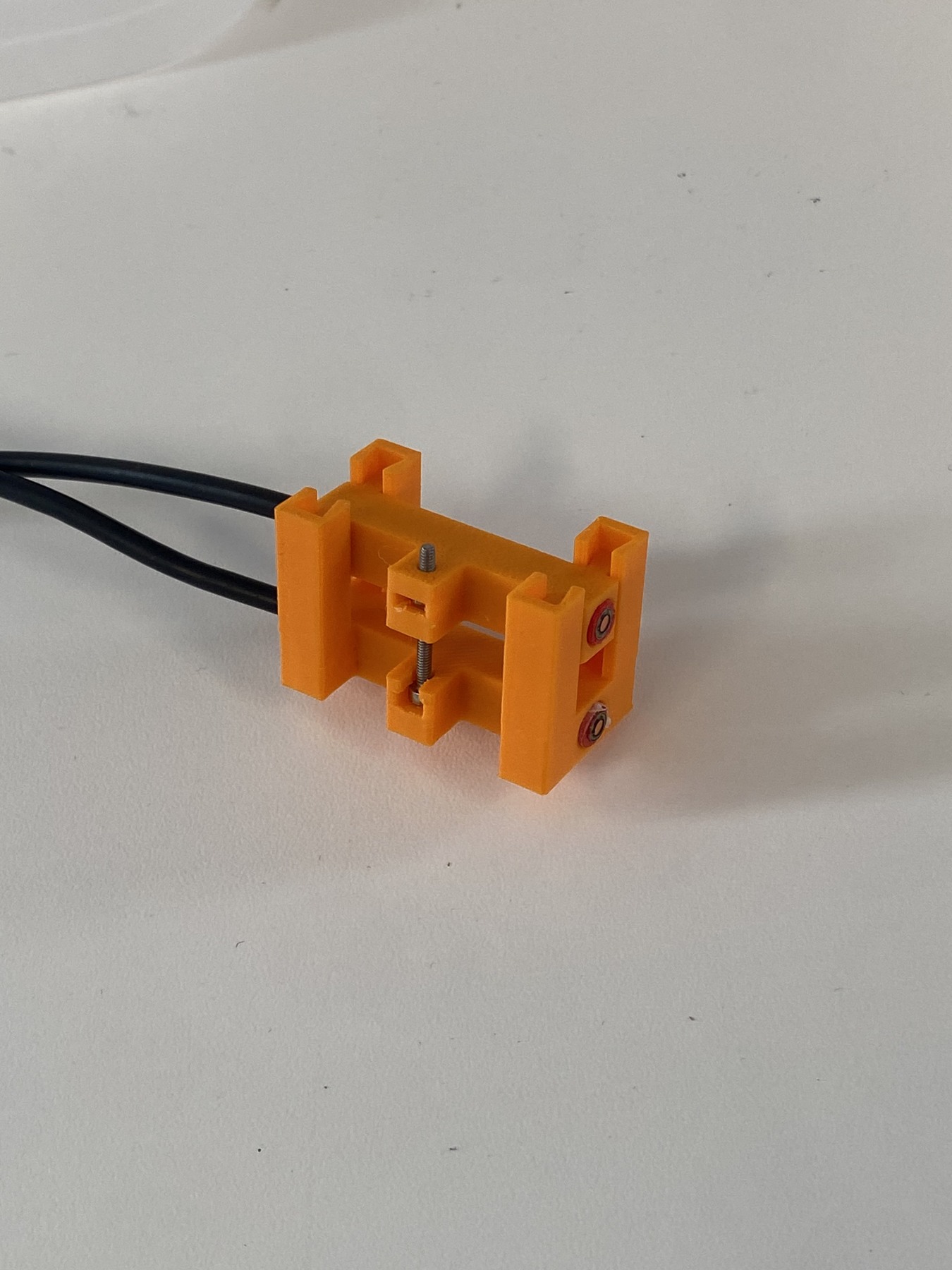
Stereoscopic viewing required two parallel borescopes with adjustable spacing, without axial twisting.

I designed a hybrid holder with a 3D-printed dovetail joint to guide linear translation and constrain rotation. A standard screw drives a press-fit nut embedded in the moving component to adjust the distance between the borescopes.

Catalog metal hardware provides the actuation; the print supplies the custom guiding geometry. The prototype combines both in an adjustable holder designed to preserve parallel optical alignment.

Orange 3D-printed holder with two installed borescopes, black cables, a screw and captured nut
Printed guidance and standard hardware, with the paired borescopes installed.

03 / McGill Design Challenge

Remote-controlled vehicle

Build for the plan.
Leave room to pivot.

A modular vehicle architecture for a constrained course — and the iterations it took to complete it.

30° incline4 motor limit$120 budget
Bar lift
Bar lift + ramp traversal + ball release · three prototype excerpts at original speedOpen video ↗
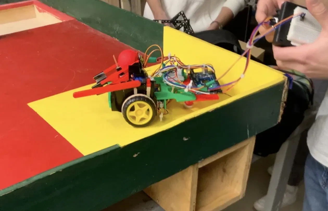
View the course photograph
Green remote-controlled prototype vehicle with lift and yellow ramp on the challenge course
Physical prototype on the challenge course
My contribution

Led the vehicle’s mechanical design, fabrication, prototype assembly and iteration, and took on a substantial share of the coding. Assisted with the ramp design.

Team contribution

Teammates contributed ramp CAD and project reporting. Course completion was the team outcome.

Adaptable architecture

Make change part
of the design.

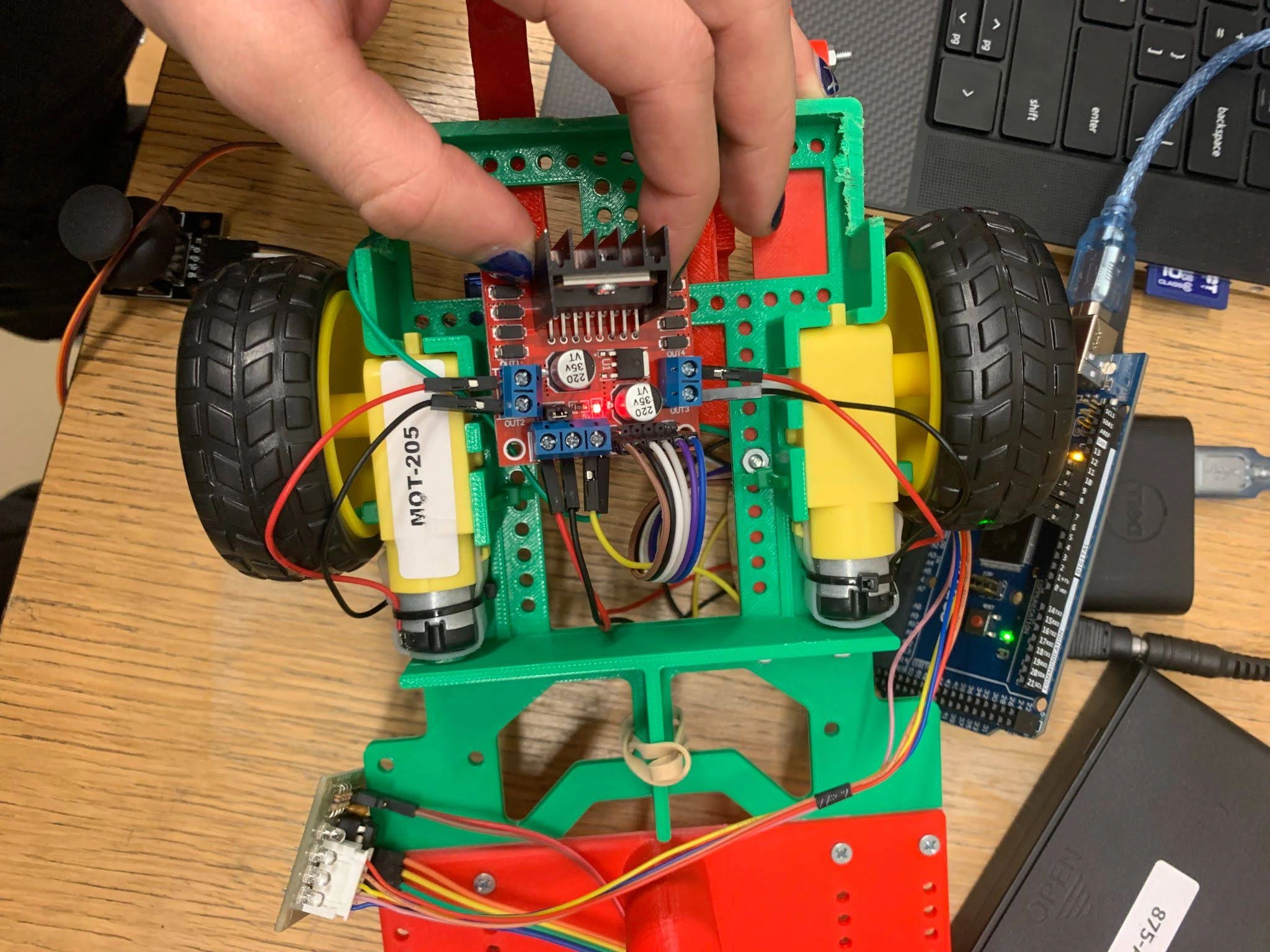
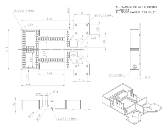
I designed a 79.4 g printed chassis with an M3 mounting grid and weight relief, giving the subsystems a common base under the challenge’s volume constraint.

When the scissor lift failed, I pivoted to a direct-drive bar lift, alongside the team’s 60° gravity ramp. Moving the 690 g power supply off the chassis reduced the weight the vehicle had to carry up the incline.

The vehicle completed all course objectives. The design lesson: a modular base makes a failed mechanism easier to replace.

Top view of the green modular chassis, mounted motors, electronics and fasteners
The mounting grid in use
Original dimensioned engineering drawing of the chassis, with top, side and isometric views
Chassis drawing · original source resolution
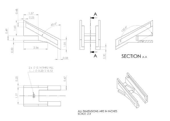
Dimensioned ball-drop mechanism drawing with orthographic views, section A–A and an isometric view; all dimensions are in inches
Ball-drop mechanism drawing

Let’s make something useful

Good engineering
starts with
a conversation.

Interested in my approach to mechanical design, medical devices or prototyping? I’d love to connect.